监测集成电路监控电池供电设备
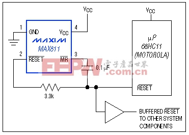
µCs such as the Motorola 68HC11 have bidirectional reset pins that may contend with active-low RESET from the supervisory IC. If the supervisor reset is high, for instance, and the µC tries to pull it low, the result may be an indeterminate logic level. Figure 8 connections allow both the supervisor and µC to assert valid resets to the system, and also ensure sufficient duration for the reset pulses (µC resets may be too short for some devices in the system).

Figure 8. These connections allow dual control of the buffered reset line, and extend the duration of resets issued by the µP.
The capacitor enables resets from the supervisor and µC to pull active-low MR low. active-low MR going low initiates a 200ms timeout within the supervisor, producing a 200ms minimum pulse at its active-low RESET terminal (pin 2) that overrides the µC active-low RESET and drives the system reset line via the buffer. active-low MR returns high as the capacitor charges. When the µC active-low RESET de-asserts following the timeout delay, the capacitor discharges through the active-low MR pull-up resistor and an internal ESD-protection diode.


评论